The hardest part of any PCB design is adding parts and components. You shouldn’t use random part libraries, and creating your own part libraries is just a pain. Why have we endured this pain for so long, especially considering that most components follow a standard? Add in the fact that 3D modeling and rendering a board in a mechanical CAD tool is now a thing, making creating your own part libraries even more involved.
To solve this problem, Autodesk has introduced library.io, a tool to parametrically generate component footprints for Eagle and 3D models for Fusion360. Given that most parts follow a standard — QFP, TO-, DFN, or SOT23 — this is now the easiest way to create a new part in Eagle with its own 3D model that allows you to bring it into mechanical CAD tools.
An overview parametric parts generation is written up on the Autodesk forums, and covers what is possible with this new tool. There are actually two distinct versions, one is a web-based app that allows you to create packages and footprints parametrically in your browser and export them as a library. The other version of the tool is integrated with Eagle and allows you to create a new component parametrically from within Eagle.
This is a far cry from the standard method of creating new footprints. Instead of toiling over a datasheet and dropping correctly sized pads onto a grid, creating a new parametric footprint is as easy as copying a few numbers. In addition to the new parametric design feature, there’s a new tool in Eagle that does away with placing and naming pins for symbols. Now you can simply cut and paste a list of pins from the datasheet.
It should be noted that everything created with the library.io tool can be downloaded and used offline. Combine that with the recent news that KiCad can now ingest Eagle board and schematic files, and you have a way to create parametric footprints in everyone’s favorite Open Source PCB tool as well.
[Conor Patrick] is no stranger to hardware development, and he’s had an interesting project for the past few months. He’s attempting to create a tool to convert images of technical drawings (such as footprints for electronic components) into digital formats that can be imported into other tools. This could automate turning a typical footprint drawing like the one shown into an actual part definition in a CAD program, which could really speed up the creation of custom parts.
Key to the entire concept is the detection of lines in a black-and-white technical drawing. To some people this won’t sound like a particularly challenging problem; choose one or another baked-in line detection function, maybe with a bit of pre or post-processing, and that should be that. It turns out that detecting lines can be harder than expected, and as usual the devil is in the detail.
When [Conor] tried some existing methods for detecting lines, the results appeared good at first but came up short in frustrating ways. Software did not appreciate that in a technical drawing, a line is a single unbroken unit from point A to point B. Without that assumption, what should be a single line sometimes had sections missing, or single lines were detected as multiple segments instead of a unit. Lines that crossed other lines complicated things. Unwanted lines like a “1” or the lower half of a “Y” were being detected. There had to be a better way.
In the end, a custom solution that took proper advantage of the nature of the source images and made the correct assumptions is what made all the difference. With some intelligent threshold setting combined with looking at vertical and horizontal line instances separately, it was possible to locate lines and their lengths far more accurately than any other method he had tried. The system doesn’t handle sloped lines yet, but it might be possible to simply iterate through rotations of the image while applying the same method. If you have a better solution, [Conor] wants to hear from you.
Digikey might wow us with their expansive stock, but now they’re wowing us with a personal gesture. The US-based electronics vendor is nodding its head in approval to KiCad users with its very own parts library. What’s more, [Chris Gammell] walks us through the main features and thought process behind its inception.
With all the work that’s going into this library, it’s nice to see features showing that Digikey took a thorough look at KiCad and how it fits into the current state of open-source PCBA design. First off, this library follows a slightly different design pattern from most other KiCad libraries in that it’s an atomic parts library. What that means is that every symbol is linked to a specific manufacturer part number and, hence, gets linked to a specific footprint. While this style mirrors EagleCad’s; KiCad libraries usually separate symbols from footprints so that symbols can be reused and parts can be more easily swapped in BOMs. There’s no “best” practice here, so the folks at Digikey thought they’d expose the second option.
Next off, the library is already almost 1000 parts strong and set to grow. These aren’t just the complete line of Yageo’s resistor inventory though. They actually started cultivating their library from the parts in Seeed Studio’s open parts library. These are components that hobbyists might actually use since some assembly services have a workflow that moves faster with designs that use these parts. Lastly, since all parts have specific vendor part numbers, BOM upload to an online cart is more convenient, making it slightly easier for Digikey to cha-ching us for parts.
Yes, naysayers might still cry “profit” or “capitalism” at the root of this new library, but from the effort that’s gone into this project, it’s a warm gesture from Digikey that hits plenty of positive personal notes for hobbyists. Finally, we can still benefit from plenty of the work that’s gone into this project — even if we don’t use it as intended. The permissive license lets us snag the symbols and reuse them however we like. (In fact, for the sharp-eyed legal specialists, they actually explicitly nullified the clause stating that derivative projects need not be licensed with a creative-commons license.)
With maturing community support from big vendors like Digikey, we’re even hungrier to get our hands on KiCad V.
Let’s get this out of the way first – this project isn’t meant to be a replacement for your regular smartphone. Although, at the very least, you can use it as one if you’d like to. But [Shree Kumar]’s Hackaday Prize 2018 entry, the Kite : Open Hardware Android Smartphone aims to be an Open platform for hackers and everyone else, enabling them to dig into the innards of a smartphone and use it as a base platform to build a variety of hardware.
When talking about modular smartphones, Google’s Project Ara and the Phonebloks project immediately spring to mind. Kite is similar in concept. It lets you interface hacker friendly modules and break out boards – for example, sensors or displays – to create your own customized solutions. And since the OS isn’t tied to any particular brand flavor, you can customize and tweak Android to suit specific requirements as well. There are no carrier locks or services to worry about and the bootloader is unlocked.
Hackaday Show-n-Tell in Bangalore
At the core of the project is the KiteBoard – populated with all the elements that are usually stuffed inside a smartphone package – Memory, LTE/3G/2G radios, micro SIM socket, GPS, WiFi, BT, FM, battery charging, accelerometer, compass, gyroscope and a micro SD slot. The first version of KiteBoard was based around the Snapdragon 410. After some subtle prodding at a gathering of hackers in Bangalore, [Shree] moved over to the light side, and decided to make the KiteBoard V2 Open Source. The new board will feature a Snapdragon 450 processor among many other upgrades. The second PCB in the Kite Project is a display board which interfaces the 5″ touchscreen LCD to the main KiteBoard. Of Hacker interest is the addition of a 1080p HDMI output on this board that lets you hook it up to external monitors easily and also allows access to the MIPI DSI display interface.
Finally, there’s the Expansion Board which provides all the exciting hacking possibilities. It has a Raspberry Pi compatible HAT connector with GPIO’s referenced to 3.3 V (the KiteBoard works at 1.8 V). But the GPIO’s can also be referenced to 5 V instead of 3.3 V if you need to make connections to an Arduino, for example. All of the other phone interfaces are accessible via the expansion board such as the speaker, mic, earpiece, power, volume up / down for hacking convenience. The Expansion board also provides access to all the usual bus interfaces such as SPI, UART, I²C and I²S.
To showcase the capabilities of the Kite project, [Shree] and his team have built a few phone and gadget variants. Build instructions and design files for 3D printing enclosures and other parts have been documented in several of his project logs. A large part of the BoM consists of off-the-shelf components, other than the three Kite board modules. If you have feature requests, the Kite team is looking to hear from you.
When it comes to smartphone design, Quantity is the name of the game. Whether you’re talking to Qualcomm for the Snapdragon’s, or other vendors for memory, radios, displays and other critical items, you need to be toeing their line on MOQ’s. Add to this the need to certify the Kite board for various standards around the world, and one realizes that building such a phone isn’t a technical challenge as much as a financial one. The only way the Kite team could manage to achieve their goal is to drum up support and pledges via a Kickstarter campaign to ensure they have the required numbers to bring this project to fruition. Check them out and show them some love. The Judges of the Hackaday Prize have already shown theirs by picking this project among the 20 from the first round that move to the final round.
KiCad, the open source EDA software, is popular with Hackaday readers and the hardware community as a whole. But it is not immune from the most common bane of EDA tools. Managing your library of symbols and footprints, and finding new ones for components you’re using in your latest design is rarely a pleasant experience. Swooping in to help alleviate your pain, [twitchyliquid64] has created KiCad Database (KCDB). a beautifully simple web-app for searching component footprints.
The database lets you easily search by footprint name with optional parameters like number of pins. Of course it can also search by tag for a bit of flexibility (searching Neopixel returned the footprint shown above). There’s also an indicator for Kicad-official parts which is a nice touch.One of our favourite features is the part viewer, which renders the footprint in your browser, making it easy to instantly see if the part is suitable. AngularJS and material design are at work here, and the main app is written in Go — very trendy.
The database is kindly publicly hosted by [twitchyliquid64] but can easily be run locally on your machine where you can add your own libraries. It takes only one command to add a GitHub repo as a component source, which then gets regularly “ingested”. It’s great how easy it is to add a neat library of footprints you found once, then forget about them, safe in the knowledge that they can easily be found in future in the same place as everything else.
KiCad Version 5 has been released! Footprints are going to be installed locally, and the Github plugin for library management is no longer the default. You now have the ability to import Eagle projects directly, Eeschema has a better configuration dialog, better wire dragging, and Pcbnew now has complex pad shapes. The changelog also says they’ve gone from pronouncing it as ‘Kai-CAD’ to ‘Qai-CAD’.
Kids can’t use computers because of those darn smartphones. Finally, the world is ending not because of Millennials, but because of whatever generation we’re calling 12-year-olds. (I’m partial to Generation Next, but that’s only because my mind is polluted with Pepsi commercials from the mid-90s.)
Need a NAS? The Helios4 is built around the Marvell Armada 388 SoC and has four SATA ports, making it a great way to connect a bunch of hard drives to a network. This is the second run from the team behind the Helios, and now they’re looking to take it into production.
A while ago, [Dan Macnish] built Draw This, a camera that takes an image, sends it through artificial intelligence, and outputs a cartoon on a receipt printer. It’s a camera that prints pictures of cartoons. Of course, some people would want to play with this tech without having to build a camera from scratch, so [Eric Lu] built Cartoonify, a web-based service that turns pictures into cartoons.
Grafitti is fun to spell and fun to do, and for all the proto-Banskys out there, it’s all about stencils. [Jeremy Cook] did a quick experiment with a 3D-printed spray paint stencil. It works surprisingly well, and this is due to leveraging the bridging capability of his printer. He’s putting supports for loose parts of the stencil above where they would normally be. The test sprays came out great, and this is a viable technique if you’re looking for a high-quality spray paint stencil relatively easily.
Another holy scroll for the Church of Robotron. PoC || GTFO is a semi-annual journal of hardware exploitation, and something you must read. About a year ago, No Starch Press released the first Bible of PoC || GTFO, and now it’s time for a new testament. PoC || GTFO Volume 2 is out now, covering Elegies of the Second Crypt War to Stones from the Ivory Tower, Only as Ballast. It’s still Bible-shaped, with a leatherette cover and gilt edges.
KiCad version 5 is out, and you know what that means: It’s time to start on version 6. To that end, CERN has opened up the floodgates where you, yes, youcan donate to KiCad development. The team is looking for 600 hours of development and 30,000 Swiss Francs or about that many US Dollars. As of this writing (last Wednesday), more than 200 people have donated, at an average donation per person of about 80 CHF.
Oh good, this is finally over. Qualcomm will not be buying NXP. Previously, Reuters reported Qualcomm would purchase the other semiconductor manufacturer for $38 Billion, the largest semiconductor deal ever. There were earlier rumors of an acquisition. The deal was struck down by Chinese regulators, and speculation rages that this is a reaction to the US/China trade war. Qualcomm now has to pay NXP $2 Billion in fees, which they could use to dig out some of the unobtanium Motorola datasheets locked away in a file cabinet.
The uStepper (or μStepper, whatever) is a neat little add-on to standard NEMA stepper motors. It bolts to the back and gives you the ability to control a stepper over a standard serial bus, with a built-in encoder. Now there’s a new Kickstarter for an improved version that uses the Trinamic TMC2208 ‘silent’ motor driver. That Kickstarter is just a draft now, but if you’re planning a 3D printer build, this could be what you’re waiting for.
We’ve all been there; you finally get the last DigiKey box and now your desk is covered in parts to stuff into a shiny new PCB you’ve been working on. First stop? Passive town, population endless waves of 1uF capacitors. The first one goes in the upper left, then a little below that, then… once you get to C157 it’s getting pretty hard to remember exactly which parts go where. Enter the literally named InteractiveHtmlBom (IHB) to smooth this process out.
IHB makes the frustrating task of mapping lines in a BOM to a physical position on a board easy. The classic method is of course, to look at the BOM, then search the board for that designator and place the component. (You left the designators in the silk, right?) Or to look at the BOM, ask your CAD package to search for that part in the layout, then place. IHB generates a document that does this automagically.
Run the tool, either standalone or as a plugin for KiCAD 5.0, and you get a folder with the new interactive BOM in it. There are a few view options but generally it presents a view of the BOM with designators and value in one pane and a wonderful render of the top and/or bottom of the board in another pane. When you hover over a BOM line it highlights the relevant parts in the board view! There are toggles for filtering by top and bottom of board, marking which parts have been placed, light and dark mode, etc. Plus the ability to filter and sort by designator and value. We would have been impressed if it was just a generator/viewer for those slick scrollable/pannable board renders!
Check out a very long GIF demo after the break, or explore one of many pre-created demo BOMs here. We’re partial to the OSPx201.
Last time we talked about a KiCAD tool it was to describe a way to make the zen-like task of manual assembly more convenient. But what about that most onerous of EE CAD tasks, part creation? Home makers probably don’t have access to expensive part library subscriptions or teams of people to create parts for them, so they are left to the tedium of creating them by hand. What if the dream tool existed that could read the darn PDF by itself and make a part? It turns out [Sébastien] made that tool and it’s called uConfig.
uConfig has a pretty simple premise. It scrapes manufacturer datasheets in PDF form, finds what it thinks are diagrams of parts with pin names, functions, etc, and emits the result as parts in a KiCAD library. To aid in the final conversion [Sébastien] added rules engine which consume his custom KiCAD Style Sheets which specify how to categorize pins. In the simple case the engine can string match or use regex to let you specify things like “all pins named VDD[A-C] should be power pins”. But it can also be used to move everything it thinks belongs to “GPIOB” and stick them on the bottom of the created symbol. We could imagine features like that would be of particular use breaking out gigantic parts like a 400 ball BeagleBone on a chip.
When writing software a key part of the development workflow is looking at changes between files. With version control systems this process can get pretty advanced, letting you see changes between arbitrary files and slices in time. Tooling exists to do this visually in the world of EDA tools but it hasn’t really trickled all the way down to the free hobbyist level yet. But thanks to open and well understood file formats [jean-noël] has written plotgitsch to do it for KiCAD.
In the high(er)-end world of EDA tools like OrCAD and Altium there is a tight integration between the version control system and the design tools, with the VCS is sold as a product to improve the design workflow. But KiCAD doesn’t try to force a version control system on the user so it doesn’t really make sense to bake VCS related tools in directly. You can manage changes in KiCAD projects with git but as [jean-noël] notes reading Git’s textual description of changed X/Y coordinates and paths to library files is much more useful for a computer than for a human. It basically sucks to use. What you really need is a diff tool that can show the user what changed between two versions instead of describe it. And that’s what plotgitsch provides.
plotgitsch’s core function is to generate images of a KiCAD project at arbitrary Git revisions. After that there are two ways to view the output. One is to generate images of each version which can be fed into a generic visual diff tool (UNIX philosophy anyone?). The documentation has an example script to help facilitate setting this up. The other way generates a color coded image in plotgitsch itself and opens it in the user’s viewer of choice. It may not be integrated into the EDA but we’ll take one click visual diffs any day!
For most developers “distributed version control” probably means git. But by itself git doesn’t work very well with binary files such as images, zip files and the like because git doesn’t know how to make sense of the structure of an arbitrary blobs of bytes. So when trying to figure out how to track changes in design files created by most EDA tools git doesn’t get the nod and designers can be trapped in SVN hell. It turns out though KiCAD’s design files may not have obvious extensions like .txt, they are fundamentally text files (you might know that if you’ve ever tried to work around some of KiCAD’s limitations). And with a few tweaks from [jean-noël]’s guide you’ll be diffing and merging your .pro’s and .sch’s with aplomb.
There are a couple sections to the document (which is really meant as an on boarding to another tool, which we’ve gotten to in another post). The first chunk describes which files should be tracked by the repo and which the .gitignore can be configured to avoid. If that didn’t make any sense it’s worth the time learning how to keep a clean repo with the magic .gitignore file, which git will look for to see if there are any file types or paths it should avoid staging.
The second section describes how you can use two nifty git features, cleaning and smudging, to dynamically modify files as they are checked in and out of the repo. [jean-noël]’s observation is that certain files get touched by KiCAD even if there are no user facing changes, which can clutter patch sets with irrelevant changes. His suggested filters prevent this by stripping those changes out as files get checked in. Pretty slick.
For anyone out there who has ever struggled finding a part for Eagle or KiCad, there are some who would say you’re doing it wrong. You’re supposed to make your own parts if you can’t find them in the libraries you already have. This is really the only way; PCB design tools are tools, and so the story goes you’ll never be a master unless you can make your own parts.
That said, making schematic parts and footprints is a pain, and if there’s a tool to automate the process, we’d be happy to use it. That’s exactly what uConfig does. It automatically extracts pinout information from a PDF datasheet and turns it into a schematic symbol.
uConfig is an old project from [sebastien caux] that’s been resurrected and turned into an Open Source tool. It works by extracting blocks of text from a PDF, sorts out pin numbers and pin labels, and associates those by the relevant name to make pins. It’s available as a pre-built project (for Windows, even!), and works kind of like magic.
The video demo below shows uConfig importing a PDF datasheet — in this case a PIC32 — automatically extracting the packages from the datasheet, and turning that into a schematic symbol. It even looks as if it’ll work, too. Of course, this is just the schematic symbol, not the full part including a footprint, but when it comes to footprints we’re probably dealing with standard packages anyway. If you’re looking to build a software tool that takes a datasheet and spits out a complete part, footprint and all, this is the place to start.
The first thing you probably asked yourself when learning how to lay out PCBs was “can’t the computer do this?” which inevitably led to the phrase “never trust the autorouter!”. Even if it hooks up a few traces the result will probably be strange to human eyes; not a design you’d want to use.
But what if the autorouter was better? What if it was so far removed from the autorouter you know that it was something else? That’s the technology that JITX provides. JITX is a company that has developed new tools that can translate a coarse textual specification of a board to KiCAD outputs autonomously.
The JITX DSL
How do you use JITX? At this point the company provides a front end to their tools; you use their website contact form to talk to a human (we assume) about what you want to make and how. But watching their demo videos (see the bottom of this post) gives a hint about how the tooling actually works. In brief; it takes a specification in a domain specific language that describes the components to use, then compiles (synthesizes?) that into KiCAD files that can be sent to fab.
Removing the Human from the Equation
What level of abstraction does JITX work at? If it was an autorouter you’d select components and do some floor planning to place components before hitting the go button and getting a coffee, maybe even lay down some of the more complex tracks. That is to say, there is no abstraction at all. JITX can operate at a much higher level. You can specify which parts go exactly where and use it as an autorouter but where the tool shines is when the human specifies less, not more. The user can plug in specific components, board outlines and the like. But they can also just say “micro USB connector” and “Teensy 3.6” and JITX will figure out what connects where, place components, lay out tracks, and crop to a board outline.
But it can go even higher level than that. [Duncan] the founder and CEO told IEEE that you can “request a board with BLE and a microphone” and the tool can do everything else. It will select parts, figure out support infrastructure like power supplies, place the components, route the board, and emit design files. That’s damn near the entire design from napkin to product, which incidentally is a service JITX offers.
Boards designed by the JITX process
Control Freak v Push Button Designs
So the next question is who is this for? We have electrical engineers who may feel somewhat displaced by a technology that replaces large parts of their workflow. Even if they used it, do they effectively become programmers? Or HDL-authors (nowadays engineers who write HDL would be working on FPGAs or similar)? One could imagine an EE using a tool like JITX to augment their process by designing the totally bone-headed parts of a project which require no creativity. We’re not sure JITX would agree, but the not-groundbreaking-design market seems pretty large; enormous in fact. Especially when you consider that it includes entire products that are unsexy to an engineer but still need to be created. It might even include empowering people and organizations who would not have considered making hardware before.
Anyway, what does that market look like? Let’s consider a few examples:
There’s often a need to make little bits of connective tissue in the form of simple boards with funky connectors to adapt between arbitrary connectors. A tool that could take, for instance, DigiKey part numbers and excrete design files for production could be a nice streamline. The end game here might be getting the board fabbed and assembled too, so the process would be completely turn key. Though such a product would need to be extremely fast or it might only be useful for nasty fine pitch connectors which are hard to prototype by hand.
The firmware engineer who needs a test board made. Some firmware engineers do the electrical CAD to make a board themselves, but early prototypes are usually constructed by bolting together development boards. This is a great solution! But if a tool existed that effectively did the same thing but output a PCB instead we could imagine it finding traction.
The largest and most terrifying market might be the Generic IoT Device. How many times does an EE really need to design something with a modularized nRF52, pick-your-favorite-sensor, and a coin cell? If JITX could generate form-factor designs with common “generic” devices like this it would probably be a huge leg up for a certain class of simple product.
Looking at theJITX website, they actually offer all of these in a pretty interesting fixed pricing model. Interconnect boards are “Adapters” and are a set at $499 a design given certain constraints. They also offer to design entire PCBAs below a certain complexity in 24 hours and at a constant $3,000. It sounds like a napkin sketch is all that’s required to make a board.
We’re pretty excited about what the future holds for more intelligent design tools! Tell us what you think you might use a tool like JITX for (or not!) in the comments.
Check out this demo video which includes a literal napkin sketch. It includes some description of the DSL used to specify the board (an expanse of FR4 to connect a bunch of dev boards together). They move on to specifying the parts instead of breakouts and use the tool to redesign the board at that granularity.
CircuitPython is becoming a thing! CircuitPython was originally developed from MicroPython and ported to various ARM boards by Adafruit. Now, SparkFun is shipping their own CircuitPython board based on the nRF52840, giving this board an ARM Cortex-M4 and a Bluetooth radio.
You like contests, right? You like circuit boards too, right? Hackster.io now has a BadgeLove contest going on to create the Blinkiest Badge on Earth. Yes, this is a #badgelife contest, with the goal of demonstrating how much you can do in a single circuit badge. Prizes include a trip to San Francisco, a badass drone, a skateboard, a t-shirt, or socks. YES, THERE ARE SOCKS.
We have a date for the Vintage Computer Festival Pacific Northwest 2019. It’s going down March 23 and 24 at the Living Computers Museum in Seattle. The call for exhibitors is now open so head over and check it out. So far the tentative list of exhibits and presenters include Attack of the SPARC Clones, and I must mention that SPARC systems are showing up on eBay with much higher frequency lately. I have no idea why.
Need another con? How about a KiCAD con? The inaugural conference for KiCAD users is happening next April in Chicago and the call for talk proposals just opened up. The con focuses on topics like using KiCAD in a manufacturing setting, what’s going on ‘under the hood’ of KiCAD, and how to use KiCAD to make an advanced product.
Spanish police have stopped a homemade scooter. Someone, apparently, was tearing around a public road in Galacia on a homemade scooter. From the single picture, we’re going to say ‘not bad.’ It’s a gas-powered weed wacker mounted to a homemade frame.
Every year, in December, we take a look back at what Hackaday has accomplished in the past twelve months. Sure, we gave out hundreds of thousands of dollars in awards in the Hackaday Prize, and yes, we’ve pushed our coverage of tech advancements into weird, uncharted, but awesome territory. Our biggest accomplishment, though, is always how many readers we reach. This year, we had a slight fall-off in our readership in the Democratic People’s Republic of North Korea. We’re down from 156 views in 2017 to 75 views this year. While the year isn’t over, we don’t expect that number to change much. What was the cause of this drop-off? We’re not quite sure. Only time will tell, and we’re looking forward to serving fresh hacks every day to the DPRK in 2019.
Having stuffed ourselves full of treats through the holidays, followed by sleeping through the calm winter months, we find ourselves once again facing the overwhelming tsunami of conference season. This year things are heating up early, and you’ll find a lot of Hackaday staff are headed to Chicago for KiCon.
Now that early selection of talks has been released, the end of April can’t come soon enough. Being user focused the conference is centered around what people make using the tool, and how it can be leveraged to improve your next project. Wayne Stambaugh, the project lead for KiCad itself, will be on hand to talk about the state of the tool and what the road map looks like from here. There will be a pair of talks on effective version control and applying the practice of continuous integration and deployment to the EDA world. We’ll hear about methods for working with distributed project members and tips for designing easy to learn beginner soldering kits. And there will be two talks on RF and microwave design, one of which we hope will teach us how to use that mysterious toolbar with the squiggly lines.
For an extra dash of flavor there will be a few Hackaday staff participating in the festivities. Anool Mahidharia is making the flight over to present a talk about how to quickly generate and use 3D models in FreeCAD, something we’re very interested in applying to our messy part libraries. Kerry Scharfglass will be around to walk through how to lay out a manufacturing line and design the test tools that sit on it. And our illustrious Editor in Chief Mike Szczys will be roaming the halls in search of excellent hacks to explore and brains to pick.
Interested in attending or volunteering for the conference? Now is the time to buy your tickets and/or apply as a volunteer!
Of course there’s a ton of fun and games that surround KiCon. Hackaday will be hosting another edition of our always exciting bring-a-hack the evening of Saturday April 27th after official activities wrap up. Plan to stop by and enjoy a beverage at this gathering of like minded hackers who are showing off awesome toys. We’ll get more location details out soon, but for now, grab a ticket to the con and make your travel arrangements.
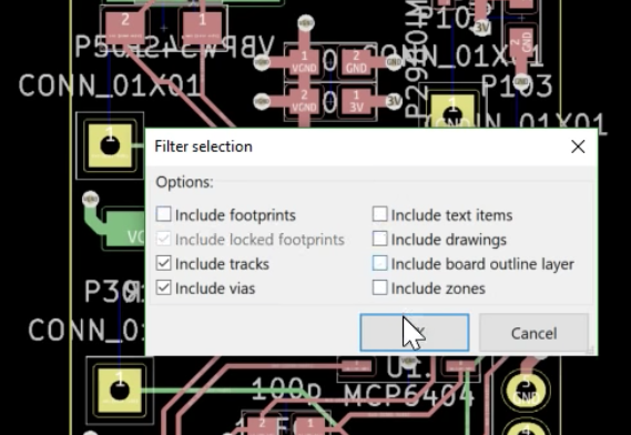
Panelization of printed circuit boards is a very helpful trick for any PCB design tool to have. By panelizing boards, you can get them ready for automated assembly. You can put testing rigs right on the panel. You can combine different boards to reduce your PCB production cost. But Eagle, Fritzing, and KiCad don’t have proper panelization tools, only hacks and third-party tools to get something close to proper panelization. [Flemming] just created a new utility for KiCad that makes multiple copies of a board connected via mouse bites. It’s not complete panelization functionality, but for a lot of us, it’ll be good enough.
The video demo for this utility (try not to click on that because we’re going to blow some bandwidth with this link) starts off by importing a board into Pcbnew, making several copies of the board, arranging these boards to have 3-4mm spacing, and drawing ‘hint lines’ for the script, telling it where the mouse bites should go. The script runs, and boom, mouse bites and a panel.
This is a KiCad specific tool, and we’ve seen other tools for KiCad that make multiple copies of a board. We’ve also seen tools that take raw Gerbers of multiple designs and turn them into a panel. [Flemming]’s efforts are the closest we’ve seen to having all the features you want out of a panelization utility bild exclusively for KiCad.
While this tool will give you a set of Gerbers with multiple copies of a board connected with mouse bites, this is not in any way a complete solution to panelizing PCBs. If you’re panelizing PCBs, you’ll want to add fiducials in the corners of the full panel, which this tool does not allow you to do. You might want to have one complete ‘frame’ as a panel — effectively a rectangular piece of fiberglass that holds all your PCBs — which this tool does not allow you to do. Since you don’t get a frame, it’s impossible to run programming or testing signals to the frame that would be needed for assembly, but not necessary in production. That said, unless you’re going to spend thousand on Altium or use Open tools that have critical flaws such as GerberPanelizer, this is the best option you’ve got.
Figuring out the maximum number of peripherals which can be sensed or controlled with a minimum number of IOs is a classic optimization trap with a lot of viable solutions. The easiest might be something like an i2c IO expander, which would give you N outputs for 4 wires (SDA, SCL, Power, Ground). IO expanders are easy to interface with and not too expensive, but that ruins the fun. This is Hackaday, not optimal-cost-saving-engineer-aday! Accordingly there are myriad schemes for using high impedance modes, the directionality of diodes, analog RCs, and more to accomplish the same thing with maximum cleverness and minimum part cost. Tucoplexing is the newest variant we’ve seen, proven out by the the prolific [Micah Elizabeth Scott] (AKA [scanlime]) and not the first thing to be named after her cat Tuco.
[Micah’s] original problem was that she had a great 4 port USB switch with a crummy one button interface. Forget replacement; the hacker’s solution was to reverse and reprogram the micro to build a new interface that was easier to relocate on the workbench. Given limited IO the Tucoplex delivers 4 individually controllable LEDs and 4 buttons by mixing together a couple different concepts in a new way.
Up top we have 4 LEDs from a standard 3 wire Charlieplex setup. Instead of the remaining 2 LEDs from the 3 wire ‘plex at the bottom we have a two button Charlieplex pair plus two bonus buttons on an RC circuit. Given the scary analog circuit the scan method is pleasingly simple. By driving the R and T lines quickly the micro can check if there is a short, indicating a pressed switch. Once that’s established it can run the same scan again, this time pausing to let the cap charge before sensing. After releasing the line if there is no charge then the cap must have been shorted, meaning that switch was pressed. Else it must be the other non-cap switch. Check out the repo for hardware and firmware sources.
Last time we talked about a similar topic a bunch of readers jumped in to tell us about their favorite ways to add more devices to limited IOs. If you have more clever solutions to this problem, leave them below! If you want to see the Twitter thread with older schematics and naming of Tucoplexing look after the break.
KiCad is the electronic design automation software that lives at the intersection of electronic design and open source software. It’s seen a huge push in development over the last few years which has grown the suite into a mountain of powerful tools. To help better navigate that mountain, the first ever KiCad conference, KiCon, is happening next week in Chicago and Hackaday is hosting one of the afterparties.
The two days of talks take place on April 26th and 27th covering a multitude of topics. KiCad’s project leader, Wayne Stambaugh, will discuss the state of the development effort. You’ll find talks on best practices for using the software as an individual and as a team, how to avoid common mistakes, and when you should actually try to use the auto-router. You can learn about automating your design process with programs that generate footprints, by connecting it through git, and through alternate user interfaces. KiCad has 3D modeling to make sure your boards will fit their intended enclosures and talks will cover generating models in FreeCAD and rendering designs in both Fusion360 and Blender. Dust off your dark arts with RF and microwave design tips as well as simulating KiCad circuits in SPICE. If you can do it in KiCad, you’ll learn about it at KiCon.
Of course there’s a ton of fun to be had as interesting hackers from all over the world come together in the Windy City. Hackaday’s own Anool Mahidharia and Kerry Scharfglass will be presenting talks, and Mike Szczys will be in the audience. We anticipate an excellent “lobby con” where the conversations away from the stages are as interesting as the formal talks. And of course there are afterparties!
Friday 4/26 Pumping Station: One, the popular Chicago hackerspace now celebrating its 10 year anniversary, is hosting an afterparty (details TBA)
Saturday 4/27: Hackaday is hosting an after party at Jefferson Tap from 6-8:30. We’re providing beverages and light food for all who attended the conference.
If you still don’t have a ticket to KiCon, you better get one right now. We’re told that you can count what’s left on two hands. Supplyframe (Hackaday’s parent company) is a sponsor of KiCon, and we have two extra tickets that came with that sponsorship. We like seeing a diverse community at these events and have saved these tickets for people from under-represented groups (such as for example women, LGBT+, and people of color) in the hardware world. Email us directly for the tickets, your information will remain confidential.
We’re looking forward to seeing everyone next week!
It’s no surprise that we here at Hackaday are big fans of Fritzing KiCad. But to a beginner (or a seasoned veteran!) the learning curve can be cliff-like in its severity. In 2016 we published a piece linking to project by friend-of-the-Hackaday [Chris Gammell] called Contextual Electronics, his project to produce formalized KiCad training. Since then the premier “Getting to Blinky” video series has become an easy recommendation for anyone looking to get started with Libre EDA. After a bit of a hiatus [Chris] is back with bite sized videos exploring every corner of the KiCad-o-verse.
A Happy [Chris] comes free with every videoThe original Getting to Blinky series is a set of 10 videos up to 30 minutes long that walks through everything from setting up the the KiCad interface through soldering together some perfect purple PCBs. They’re exhaustive in coverage and a great learning resource, but it’s mentally and logistically difficult to sit down and watch hours of content. Lately [Chris] has taken a new tack by producing shorter 5 to 10 minute snapshots of individual KiCad features and capabilities. We’ve enjoyed the ensuing wave of learning in our Youtube recommendations ever since!
Selecting traces to rip up
Some of the videos seem simple but are extremely useful. Like this one on finding those final disconnected connections in the ratsnest. Not quite coverage of a major new feature, but a topic near and dear to any layout engineer’s heart. Here’s another great tip about pulling reference images into your schematics to make life easier. A fantastic wrapped up in a tidy three minute video. How many ways do you think you can move parts and measure distances in the layout editor? Chris covers a bunch we hadn’t seen before, even after years using KiCad! We learned just as much in his coverage of how to rip up routed tracks. You get the idea.
We could summarize the Youtube channel, but we aren’t paid by the character. Head on down to the channel and find something to learn. Make sure to send [Chris] tips on content you want him to produce!
The inaugural KiCon conference is kicking off this Friday in Chicago, and KiCad aficionados from all over the world are gathering to discuss anything and everything about the cross-platform, open-source electronic design automation platform. As you’d expect, Hackaday will have a presence at the conference, including a meet and greet after party. There’ll also be talks by a couple of our writers, including Anool Mahidharia, who’ll be taking time out of his trip to the States to drop by the Hack Chat with a preview of his talk, entitled “Fast 3D Model Creation with FreeCAD”.
Join us for the KiCad and FreeCAD Hack Chat this week with your questions about KiCad and FreeCAD. If you’ve got some expertise with electronic design tools, make sure you come by and contribute to the discussion too — we’d love to hear your insights. And as always, you can get your questions queued up by leaving a comment on the KiCad and FreeCAD Hack Chat event page and we’ll put them on the list for the Hack Chat discussion.
Click that speech bubble to the right, and you’ll be taken directly to the Hack Chat group on Hackaday.io. You don’t have to wait until Wednesday; join whenever you want and you can see what the community is talking about.